
- Remove the OEM supercharger kit. This installation should not require service mode if you use a low-profile serpentine belt removal tool.
- Clamp intercooler hose lines to reduce coolant loss during disassembly.
PCV system preparation
- Prepare the OEM PCV system to route the vacuum source. Use the provided components to use the OEM PCV system and route the vacuum source to the supercharger inlet.
- Plug the OEM PCV vacuum port with the provided plug:

- Remove the OEM plug from the PCV hose connector and install the provided adapter conversion. Remove the O-rings from the OEM plug and install those to the provided barb hose adapter.


- Attach the provided hose to the PCV billet adapter. This hose will connect to the supercharger inlet hose barb. Cut hose at the SC inlet side later as needed to fit your application.
Remove OEM supercharger studs
- The OEM supercharger studs cannot be used and must be removed. Remove studs.
NOTE:
Make sure to cover intake holes while performing this procedure. This will save you from dropping tools or parts used to remove the studs.
Supercharger installation procedure: (Please follow the sequence as shown. )
- Remove the top cover and intercooler tanks from the MercRacing TVS supercharger. Keep track of the different size of bolts used.
- Mount the supercharger assembly on top of the engine, being careful to be observant of any plastic components, harnesses, and hoses. Make sure not to trap harnesses, etc.

- Hand thread the Six M8 bolts on the manifold side-tanks. Please ensure a good alignment then tighten the bolts firmly. Use a firm tightness but do not over-torque, you may use blue thread locker. (torque spec 14 to 14.7 Ft/lb)
- Insert the Intercooler tanks on each side as labeled. (passenger/driver)
- Hand tread all the M5 top bolts first (keep them loose)
- Install the front core bolts next but do not tighten.
- Tighten the three M6 bolts that hold the seal for the cores. Do not overtighten as it may strip the threads on the core.
- Tighten the rest of the top M6 bolts on the core to 5 to 6 Ft lbs.
- Remove the bypass from the OEM supercharger and place on the replacement supercharger.
- Place the top cover on the supercharger and align the bolts for the bypass and hand thread them but not tighten. Tighten the bypass last when finalizing the tightening process.
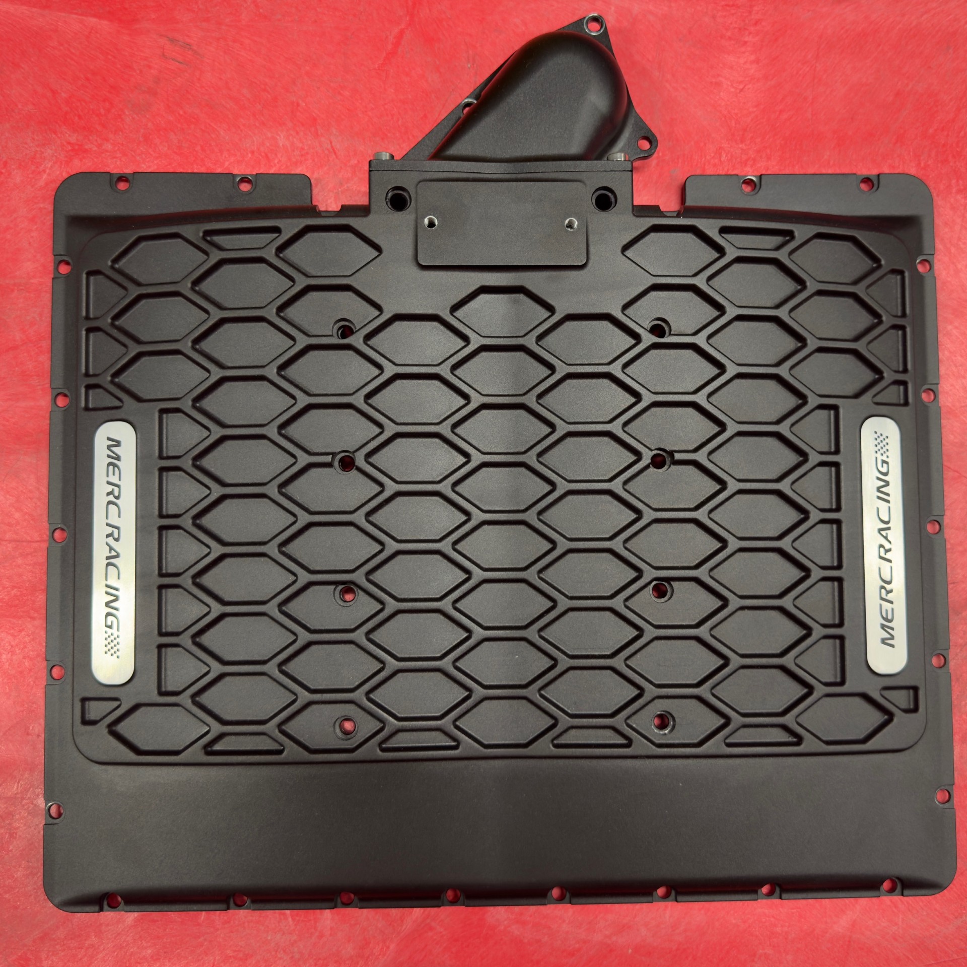
- See diagram on previous page for bolt locations. There are various sizes and must ensure the correct location for all the bolts.
- Tighten the bolts from center of plate going outwards. I would tighten it in two stages. First pass light tightness then second pass do a final firm tightening of all the cover bolts to 6 ft lb.
- Tighten the bypass bolts.
Throttle assembly and sensors
- Remove the OEM MAP/IAT sensors from the OEM supercharger and attach them to the front of the supercharger.
NOTE: You will need to remove the protective caps on the MAP/IAT sensors and flip the caps 180 degrees to allow the sensors to reach and connect to their new location.
Perform the wire repining according to install video in Audi C7 owners install video.
- Remove the OEM throttle sensor and place it onto the new supercharger inlet.
Other brackets, sensors, etc.
- There is a small sensor that attaches to a clip on the OEM supercharger inlet. It appears to be a solenoid. Cut the hard line off the sensor and use the provided silicone hose to connect the sensor to the gold throttle adapter brass fitting. This is only a prototype issue. The final revision will have provision for this at the inlet.
- There is another set of sensors and currently we do not have a provision for mounting these connectors. They will remain loose for now.
- Measure and attach the PCV vacuum line.
- You may choose to extend this and use an oil catch can system. This will help in reducing/removing oil from this path. The catch can must be a sealed type. Not open. The vacuum CFM capacity on this blower is higher in volume than the OEM blower.
Intercooler Coolant lines
- Connect the provided prototype coolant lines to the supercharger tanks. If necessary, trim the excess hose to get it closer to the supercharger—just a small amount.
- You will need to extend the intercooler hoses. The OEM lines are too small to provide the adequate flow needed and are too close to the SC.
- Please ensure that the hoses clear the supercharger pulley. Use some zip ties where necessary. You may need to get creative to ensure the hose that goes under the blower snout does not touch the pulley.
Final installation Notes
- On the B8.5 S4, you will likely notice the blower corners touch the hood insulation pad. On my testing, this never caused any issues, noise, or pushed into the hood.